Gain Confidence in Millimeter-Wave Wideband Measurements
2021-06-17
来源:是德科技
The instrument's specifications determine the accuracy of the test equipment. The signal analyzer's specifications are valid up to the instrument's input connectors, where the instrument sets the reference plane. Outside the test instrument, you need to consider the impact of the components in the path between the test instrument and the DUT. The impact may degrade the system's overall measurement accuracy.
WHY FREQUENCY RESPONSES MATTER
As bandwidths grow wider and frequencies soar to millimeter-wave and beyond, small margins for error on wideband measurements force RF engineers to look for new ways to reduce frequency response errors. The responses occur at different frequencies, affecting phase and amplitude responses. A signal analyzer provides an internal calibration routine to correct its frequency responses.
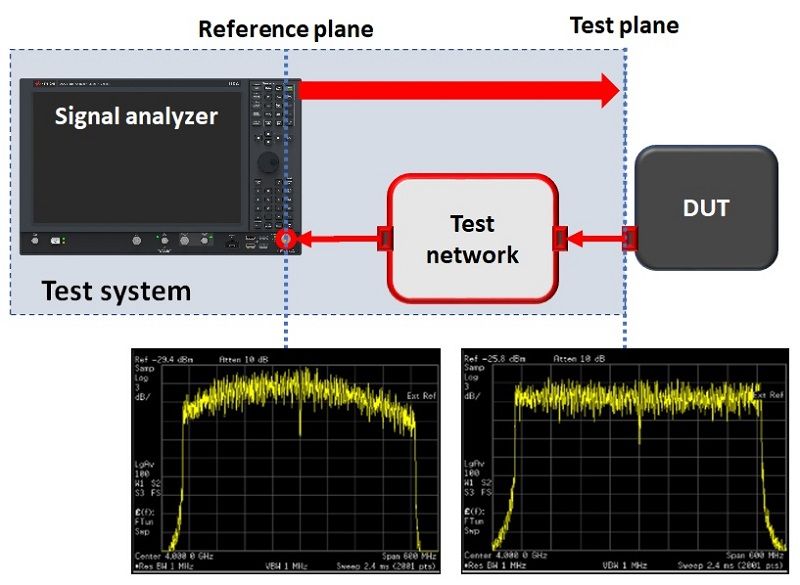
When you connect cables, connectors, switches, and fixtures in the paths between the signal analyzer and the DUT, these components can degrade measurement accuracy because of frequency response errors. You need to extend the measurement accuracy from the signal analyzer's input port (reference plane) to the DUT's test port (measurement plane), as shown in Figure 1.

Figure 1. Frequency responses of a test system
CORRECTING FREQUENCY RESPONSES
Signal analyzers allow you to configure amplitude corrections and complex corrections (amplitude and phase) to remove frequency responses. Correcting for magnitude and phase errors in the test network allows you to get the most out of your measurement and see the real performance of your device.
Using a signal generator and power sensor
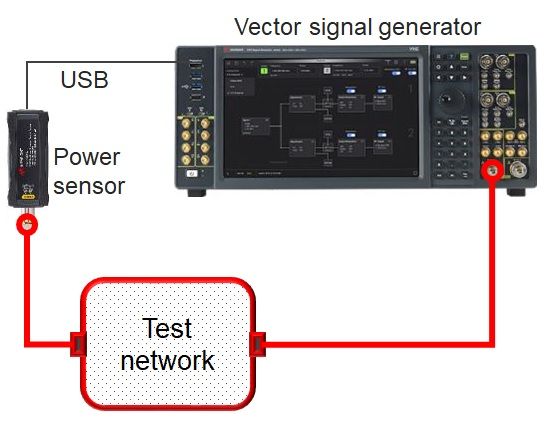
Signal analyzers allow you to configure amplitude corrections and complex corrections, including amplitude and phase corrections, to correct frequency responses. For amplitude corrections, you can measure the amplitude frequency responses of the test network using a signal generator plus a power meter and sensor as shown in Figure 2, then input the correction values to the signal analyzer.

Figure 2. Using a signal generator and power sensor for amplitude corrections
Use a vector network analyzer
For complex corrections, you can make frequency response measurements of the test network using a vector network analyzer as shown in Figure 3, and save the measurement results in the .s2p format. Keysight X-Series signal analyzers allow you to load the .s2p file and correct amplitude and phase frequency responses.

Figure 3. Using a vector network analyzer for complex corrections
Use a comb generator for complex corrections
Another calibration tactic is using a comb generator. The comb generator is a universal receiver system calibrator easily injected at the desired calibration plane (the input of the test network)。 It generates continue wave (CW) tones of known amplitude and phase, as shown in Figure 4. Figure 5 shows a signal analyzer that measures each tone's amplitude and phase at the output of the test network and compares them to the known amplitude and phase.

Figure 4. A comb generator produce tones with known amplitude and phase 
Figure 5. Using a comb generator for complex corrections
Use an RCal receiver calibrator
The U9361 RCal receiver calibrator brings accuracy, efficiency, and value to the calibration of your test receiver system by allowing you to move the reference plane to the DUT. Unlike the comb generator with a fixed tone spacing and lower power at higher frequencies, RCal can change the center frequency, and the spacing of the comb tooth is tunable, as shown in Figure 6. It is beneficial when testing wider bandwidths at higher frequencies.

Figure 6. The RCal receiver calibrator generates tones with tunable center frequency and tone spacing
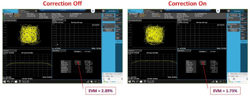
To keep your test setup efficient with the palm-sized, USB-powered and -controlled RCal, the calibrator automatically transfers data from the memory to the signal analyzer through the USB plug-and-play feature. The analyzer also autodetects the model, serial number, and options present on the calibrator. This setup can reduce the effort and complexity required to calibrate your test receiver system. Figure 7 illustrates test setups for Rcal. Figures 8 shows the EVM performance difference when the corrections are off (left) and on (right)。 The EVM performance is improved from 2.89% to 1.73%.

Figure 7. Use an RCal receiver calibrator for improving amplitude accuracy and frequency responses

Figure 8. EVM performance without and with corrections
The RCal allows you to correct absolute power accuracy, magnitude flatness, and phase flatness up to 110 GHz for the flagship N9042B UXA signal analyzer with a single device. RCal eliminates the need for multiple pieces of equipment to calibrate your signal analyzer measurement system. Learn about how to improve signal analyzer test accuracy, download the application note The Essential Guide to Receiver Calibration.


